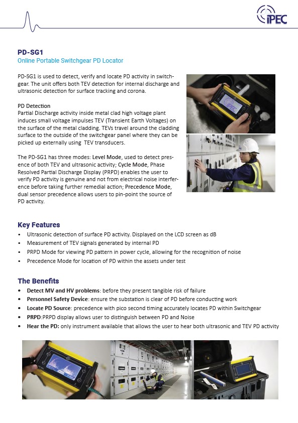
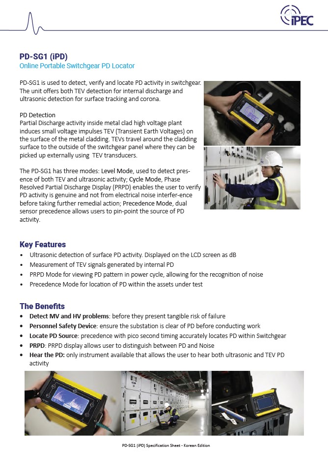
Contact us

PD-SG1

The PD-SG1 is a dual transducer Switchgear PD detection instrument. The unit detects TEV signals generated by internal discharge, as well as acoustic discharge generated by surface tracking or corona. Partial discharge activity inside metal clad high voltage plant induces small voltage impulses (called Transient Earth Voltages) on the surface of the metal cladding. TEVs travel around the cladding surface to the outside of the switchgear panel, where they can be picked up externally using capacitively coupled transducers.

PD-SG1 in action

Key Benefits

Rapidly survey the whole substation

and detect MV and HV problems before they occur

Personnel Safety Device

ensure the substation is clear of PD before conducting work

Ensure accurate results

auto separation when the device detects background Noise instead of real PD

Ergonomic and compact design

fits in the user’s pocket and Is easy to use

PD Location

locate source of Partial Discharge on switchgear panels

Spec sheet

Key Features

  • Ultrasonic detection of surface PD activity. Displayed on the LCD screen as dB reading, as well as audible signals through headphones.
  • Measurement of TEV signals generated by internal PD. Displayed on the LCD screen as dB reading.
  • Cycle Mode for viewing PD pattern in power cycle (Phi Q), allowing for the elimination of noise
  • Precedence Mode for location of PD in the assets under test
  • Bright LCD panel display for indoor and outdoor use
ipec pd-sg1

Distinguishing between Partial Discharge and Noise

The Problem

Partial Discharge (PD) is a localised breakdown of a small portion of a solid insulation system under high voltage stress. Once begun, PD causes progressive deterioration of insulating materials, ultimately leading to complete failure. It is therefore critical to be able to identify the PD source so it can be fixed quickly. However, one of the greatest problems in identifying PD is how you distinguish the discharge activity from general electrical noise (very often present in sub stations and switchgear).

The Solution

The pulses caused by each discharge are distributed across the AC power cycle in a distinctive pattern. By plotting the peak of each pulse detected, the PD-SG1 displays a pattern that can be used to distinguish between genuine Partial Discharge activity and signals from electrical noise interference.


PD-SG1

The PD-SGS is a dual transducer PD detector for Switchgear. The instrument detects TEV signals generated by internal discharge, as well as acoustic discharge generated by surface tracking or corona.

  • Measurement of TEV signals generated by internal PD
  • Ultrasonic detection of surface PD activity
  • Automatic Background Noise Detection
  • Level Mode and Trend Mode
  • Bright OLED screen display with dB readings
  • Audible output through headphones or built in speaker 

Modes of Operation

The PD-SG1 allows a 3 step approach to Switchgear Partial Discharge investigation.


PD-SG1 Readings

PD Level Mode

In Level Mode, the magnitude and the repetition rate of the PD are displayed. The dB reading gives an indication of the magnitude of the PD activity detected.

The maximum PD detected is shown on the display. The reading can be restarted at any time by selecting ‘Reset’. The repetition rate, or the ‘Count’, shows a measure of the amount of PD detected per power cycle.

PD-SG1 results

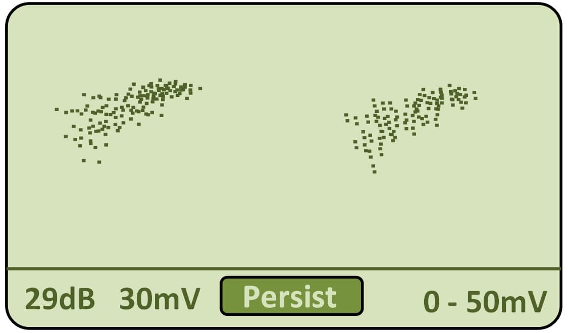
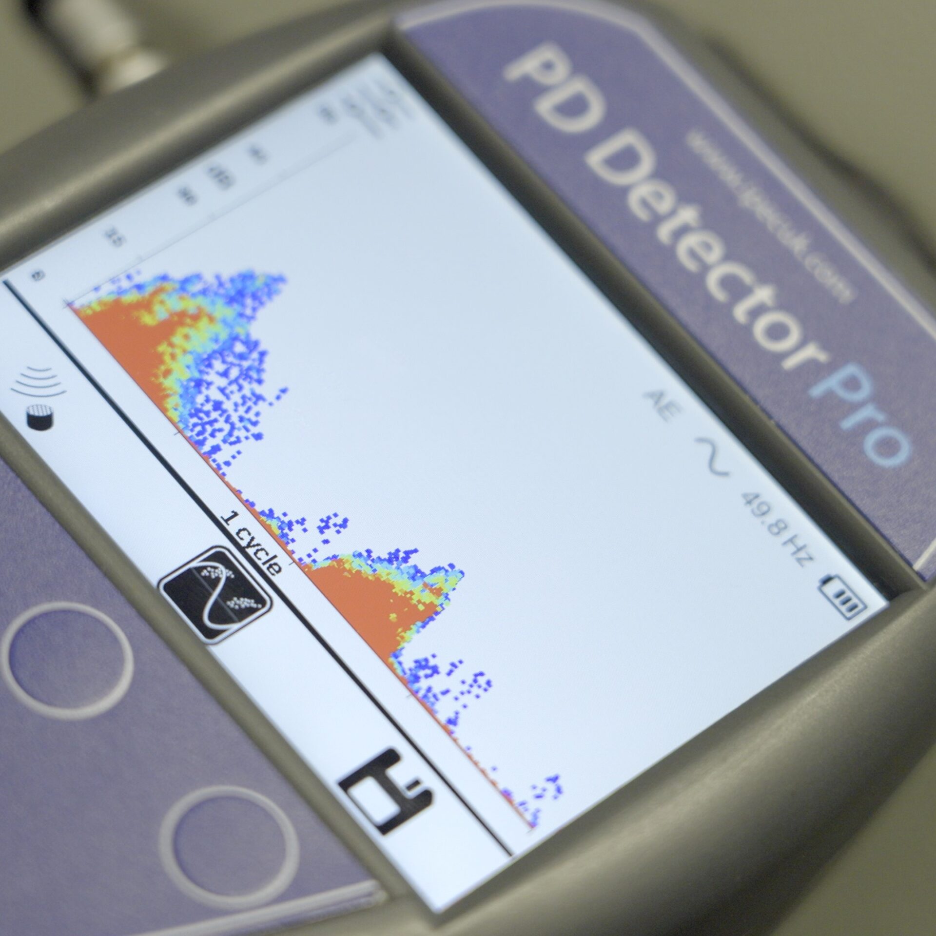
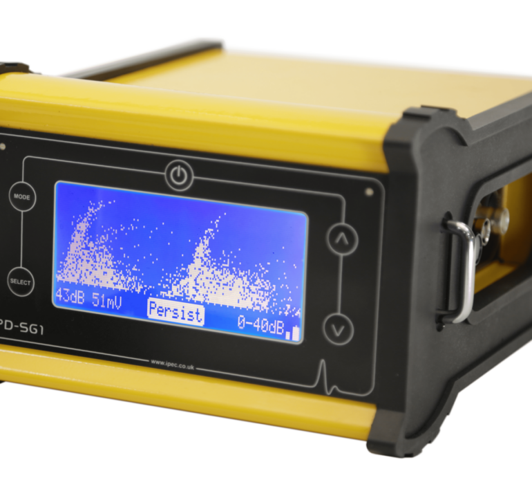
PRPD Power Cycle Mode

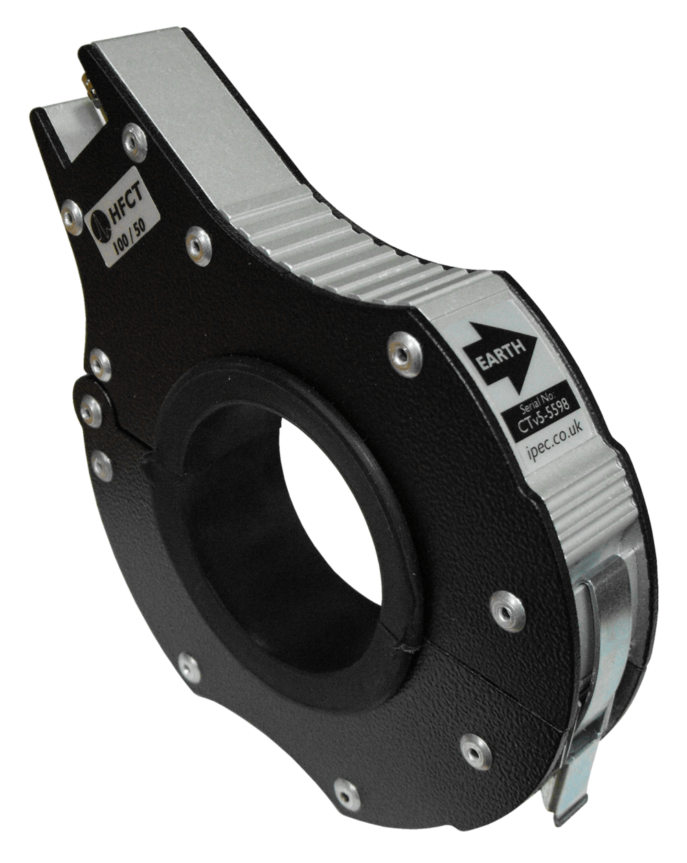
In Cycle Mode, the system shows the PD activity in a phase resolved display (φ.q) which is synchronised with the power cycle. A magnetic field detector synchronises the PD-SG1 with the current in a cable or bus bar placed nearby. The display can be set to show the activity live and constantly updated, or it can be set to infinite persistence (where an image is built up showing the distribution of activity in the power cycle).
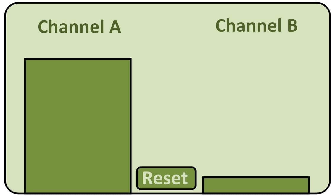
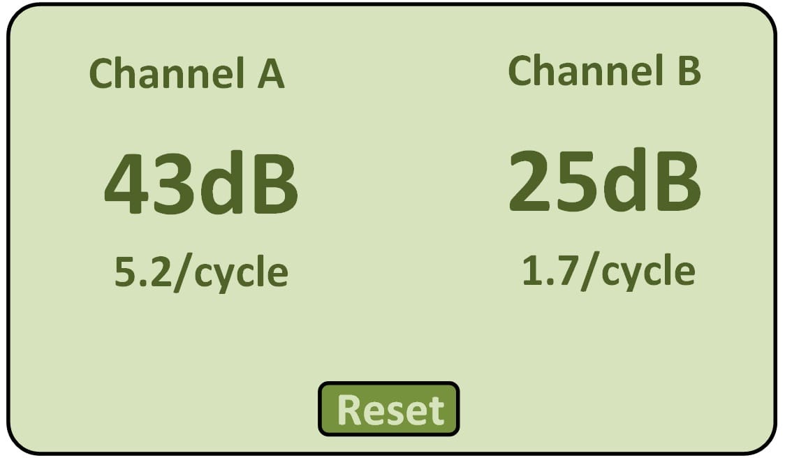
PD-SG1 Graph

PD Location Mode

Precedence Mode is used to locate the originating source of the PD activity. The display shows which sensor is closest to the source by comparing the arrival time of pulses detected on the left and right channels. As the sensors are moved around the equipment under test, the LCD display shows graphically the ratio of pulses detected on each channel. The precedent channel is also indicated with a left and a right LED, as well as acoustically via the stereo headphones.

ACCREDITATIONS