

PD on 13.8kV busbar
07 / 08 / 23
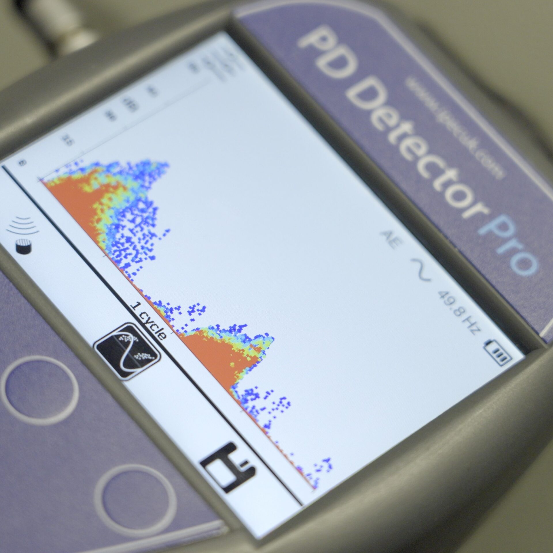
In this case extensive partial discharge damage was found on a 13.8kV busbar. The activity was picked up by PD sensors mounted inside the cable termination chambers of the switchgear.
The substation has 26 13.8kV panels all being permanently monitored for partial discharge using ultrasonic, TEV, HFCT and UHF sensors with an ASM permanent PD monitor.
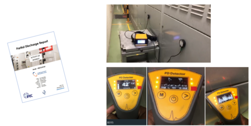
Discharge activity was detected by the ultrasonic sensors on 4 neighbouring panels, the highest being B315. Moderate levels of activity were also detected on B315 by the TEV sensor and UHF activity was picked up on multiple panels by the UHF sensors.
The image below shows the Criticality calculated by the ASM monitoring the substation before the investigation was carried out.
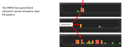
The activity was automatically classified as real PD and not noise by the ASM. The animation below for instance shows the pattern of the PRPD on the ultrasonic sensor was very clearly consistent with PD and not noise interference.
Site investigation 1
Site investigation 2
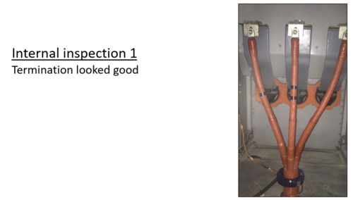
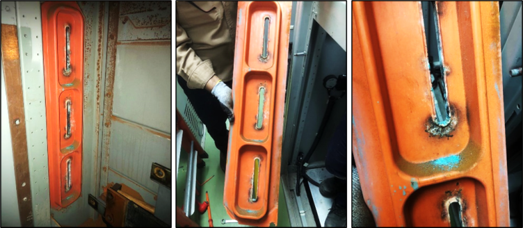
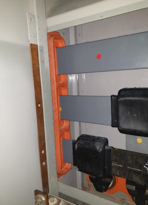
An outage was arranged and during the second site investigation the panels were opened. Visual inspection of the enclosure where the PD sensors were mounted showed no obvious damage or degradation on the B315 cable termination.
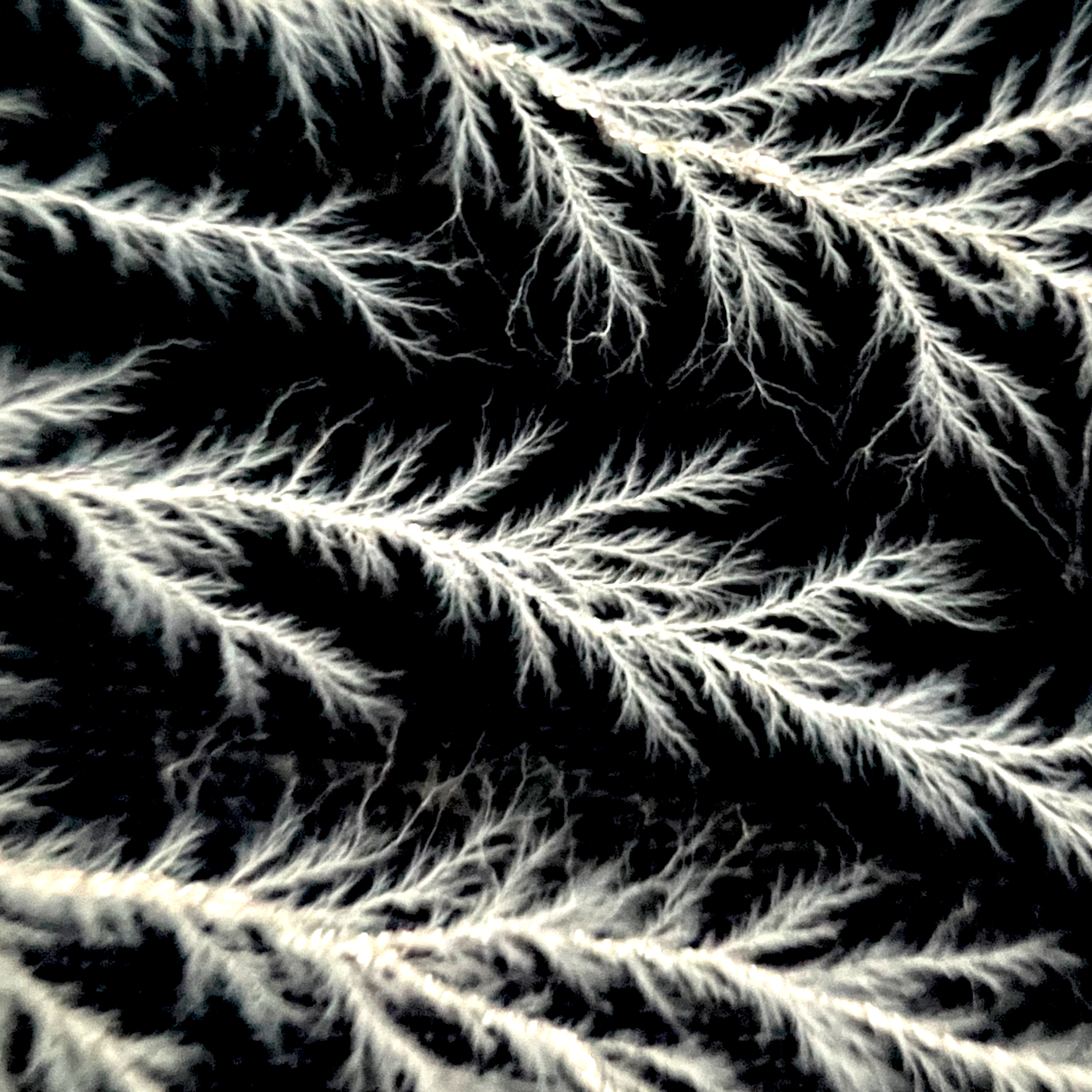
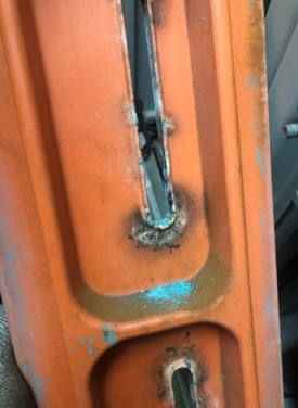
However, when the busbar chamber was inspected, extensive damage was found on the insulators that support the busbar. Verdigris was found indicating corrosion of the copper busbars and some of the internal steel panels had a lot of rust whereas there was no rust on the outside of the switchgear or on other panels. Both of these oxidisation phenomena are caused by nitric acid, that in turn is caused by partial discharge in high humidity environments.
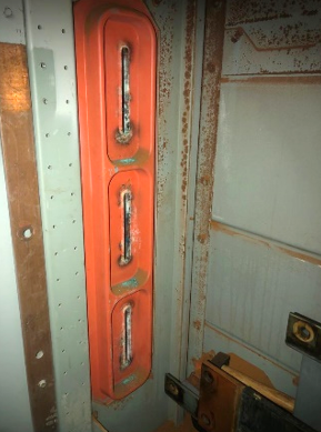
The damage extended across several panels but the worst of the damage was in panel B315 where the PD activity had been detected at the highest levels.
During the inspection a loose piece of insulator was found as shown in this video. It appears to have fallen behind the busbars and could have been responsible for initiating discharge activity.
The damaged busbars and insulators were replaced and the panel reenergised.
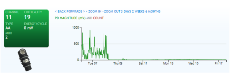
This investigation and maintenance work was carried out in early February 2023. It can be seen that the PD activity has remained low since that time.
Conclusions
It seems reasonable to conclude that an HV busbar fault was avoided in this case as the insulator degradation would have continued until it flashed over. The extent of the damage was such that it is likely that the switchgear was close to flashover at the time of intervention.
The PD results from the different PD sensors are interesting. The activity was detected by ultrasonic sensors on several panels reflecting the fact that the discharge activity was present on more than one panel and the levels were very high so there was possibly some cross-coupling.
It is also interesting to note that the PD was in a different chamber (busbar chamber) to where the ultrasonic sensors were located (cable termination). Normally a line of sight is necessary for effective ultrasonic detection but if the activity is loud enough, then so long as there is an air path between the discharge and the sensor, it can still be detected. The sound will have passed through gaps between the internal panels.
The TEV sensor on panel B315 detected the PD but signals were not as high as the ultrasonic sensors.
The UHF sensors detected the activity on many panels including some many meters away from the discharge activity. It is noticeable that there is also significant variation in the levels of activity detected on the UHF sensors. As the discharge was on the busbars, electromagnetic energy generated will have been guided along the bars away from the source. The nature of UHF pulses is such that they interact in a complex way with the surrounding environment and this energy will have propagated through the panels to where the UHF sensors were located according to the exact geometry of each panel.
Author: Dr Colin Smith, Managing Director, IPEC Ltd