

Cable Partial Discharge Sensors Application – HFCT
23 / 09 / 20
Across the HV network, there is a variety of asset types and designs. It is important to understand the best application of various IPEC sensors, in order to correctly identify how to best detect PD, and prevent failures. In this article, we will focus on discussing PD sensors – HFCT that can be used to detect PD, on-line, in cable circuits of all voltage levels from MV upwards. Typically, 3.3kV M to 750kV or higher (theoretically no limit).
High Frequency Current Transformer (HFCT)
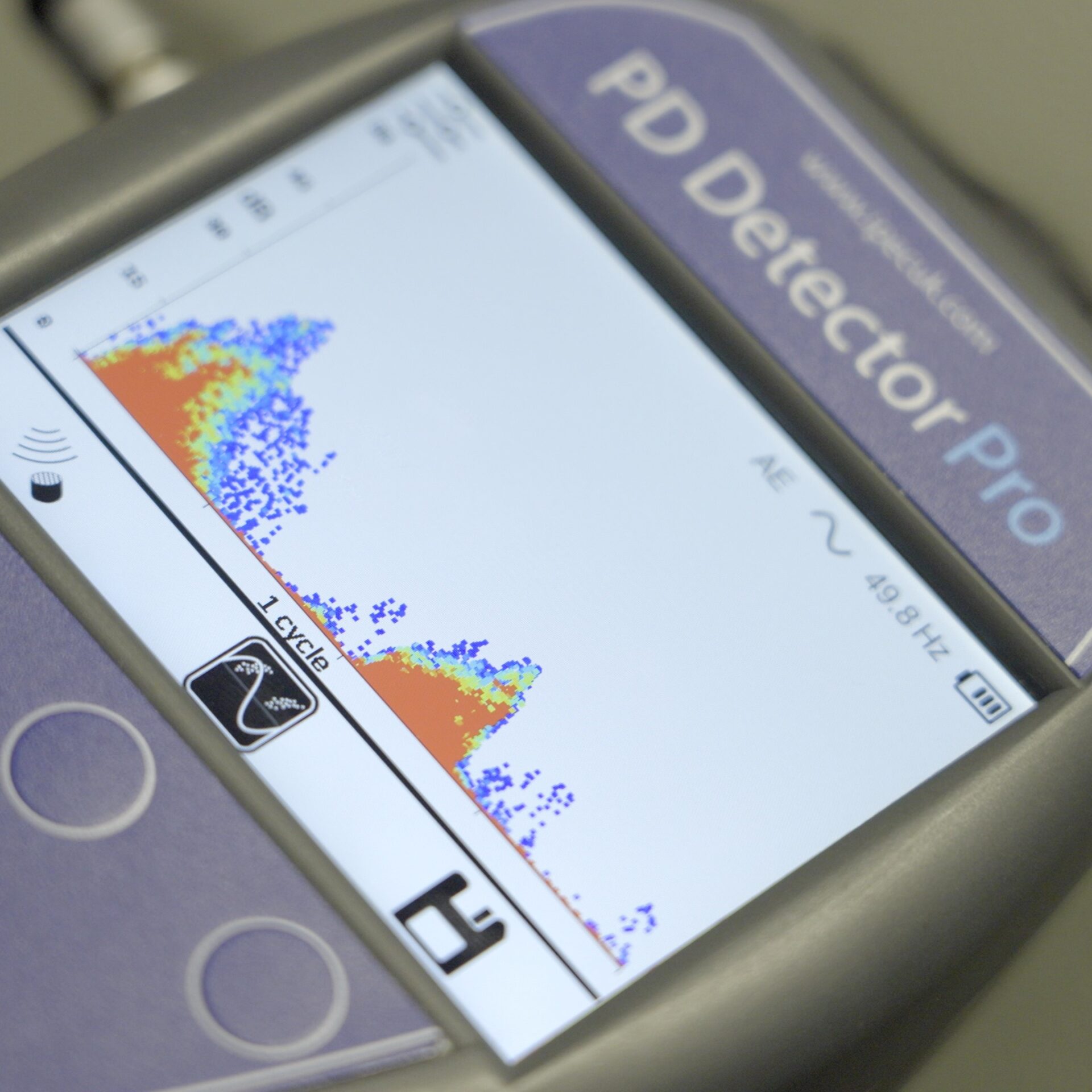
The most popular sensor for on-line cable PD detection in the market is High Frequency Current Transformer (HFCT). HFCT sensors are designed in different sizes and materials, depending on the application, but generally, they operated similarly.
HFCT sensors are installed around earth or core of cables to detect PD occurs in the inside insulation of cables. The standard detection range is 5 km or more depends on the cable condition and additional substations/impedance changes. Based on research and our experience, about 97% of cable PD occurs in cable joints or terminations, some PD will be inside pure insulation.

HFCT Sensors Installation
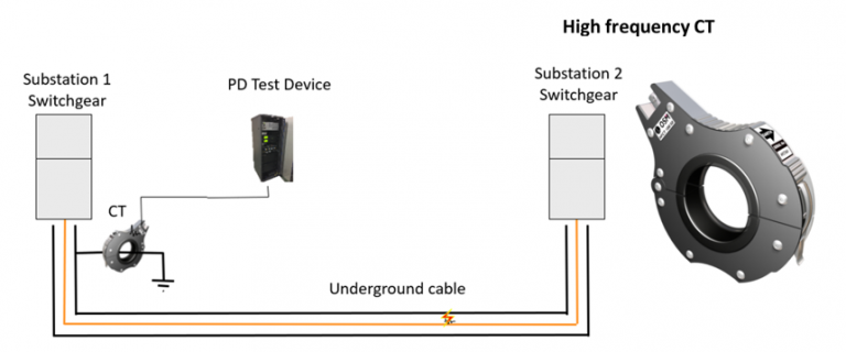
HFCT Sensors rely on detection of the PD signal, which is travelling on the earth sheath AND the core. The signals on these electrodes will be equal and opposite, so we must install HFCT where they can be separated, or where the PD may be detected in special cases.
It must be considered in each case where an HFCT can be applied, generally, at EHV level, the HFCT will be installed on cable earth no problem as earth is normally accessible and isolated properly, but at MV there can be some challenges due to earthing arrangements.
Sensor location options are as follows:
Option1 – HFCT connected around earth

Option 2 – HFCT connected around core (above earth)

Below are some diagrams of the correct and wrong HFCT installation:
Cable termination:

Wrong HFCT Installation:
- Earth and Core signal cancel each other out (+ and -)
- HFCT position above the insulation, this is very dangerous

Correct HFCT Installation:
- HFCT is installed around Earthing PD will be detected
- HFCT is installed around core PD will be detected
